This program was an introduction to PWM in order to control the brightness of an LED connected to a GPIO pin. This was also an introduction to the PWM output on a GPIO pin. The resources for the project include the C SDK User Guide, the RP2040 Datasheet and Prof. Hunter's website.
The following is the complete C code used to fade the LED in and out.
/*
 * Parth Sarthi Sharma (pss242@cornell.edu)
 * Code based on examples from Raspberry Pi Foundation.
 * The code initializes a pin to be PWM output and then
 * turns the duty cycle up and down in order to fade an LED in and out
 */
#include <stdio.h> //The standard C library
#include "pico/stdlib.h" //Standard library for Pico
#include "pico/time.h" //The pico time library
#include "hardware/irq.h" //The hardware interrupt library
#include "hardware/pwm.h" //The hardware PWM library

#define LEDPin 16 //The LED Pin

void wrapHandler(){ //The PWM wrap handler function
    static int fade = 0; //Brightness level
    static bool rise = true; //Check if fading in or out
    pwm_clear_irq(pwm_gpio_to_slice_num(LEDPin)); //Clear the interrupt flag

    if(rise){ //If the brightness is rising
        fade++; //Increment the brightness level
        if(fade > 255){ //If the fade is greater than 255
            fade = 255; //Set the fade to be 255
            rise = false; //Set flag to make brightness fall
        }
    }
    else{ //If the brightness is dalling
        fade--; //Decrement the brightness level
        if(fade < 0){ //If the fade is lesser than 0
            fade = 0; //Set the fade to be 0
            rise = true; //Set flag to make brightness rise
        }
    }

    pwm_set_gpio_level(LEDPin, fade * fade); //Set the PWM level for the slice and channel associated with a GPIO. We use a square to make the change in brightness appear linear.
}

int main(){
    gpio_set_function(LEDPin, GPIO_FUNC_PWM); //Set the LED Pin to be PWM
    uint sliceNum = pwm_gpio_to_slice_num(LEDPin); //Get PWM slice number

    pwm_clear_irq(sliceNum); //Clear the IRQ for the linked slice
    pwm_set_irq_enabled(sliceNum, true); //Enable the IRQ for the given slice
    irq_set_exclusive_handler(PWM_IRQ_WRAP, wrapHandler); //Set an exclusive interrupt handler for the interrupt
    irq_set_enabled(PWM_IRQ_WRAP, true); //Enable or disable a specific interrupt on the executing core

    pwm_config config = pwm_get_default_config(); //Get a set of default values for PWM configuration
    pwm_config_set_clkdiv(&config, 4.f); //Set clock divider in a PWM configuration
    pwm_init(sliceNum, &config, true); //Initialise a PWM with settings from a configuration object

    while(1){
        tight_loop_contents(); //Empty function
    }
}
The first lines of code in the C source file include some header files. One of these is standard C headers (stdio.h) and the others are headers which come from the C SDK for the Raspberry Pi Pico. The first of these, pico/stdlib.h is what the SDK calls a "High-Level API." These high-level API's "provide higher level functionality that isn’t hardware related or provides a richer set of functionality above the basic hardware interfaces." The architecture of this SDK is described at length in the SDK manual. All libraries within the SDK are INTERFACE libraries.
The next includes pull in hardware APIs which are not already brought in by pico/stdlib.h. These include hardware/irq.h, hardware/pwm.h and pico/time.h. As the names suggest, these interface libraries give us access to the API's associated with the hardware PWM, hardware IRQ and pico time on the RP2040.
Don't forget to link these in the CMakeLists.txt file!
#include <stdio.h>
#include "pico/stdlib.h"
#include "pico/time.h"
#include "hardware/irq.h"
#include "hardware/pwm.h"
The next section of the code is basically a single line which #define's the LED pin number (GPIO 16 in this case).
#define LEDPin 16
The wrapHandler() is the function that is called every time the PWM timer throws an interrupt. This function has two static variables: fade and rise. The fade variable is used to keep a track of the brightness level of the LED. The rise variable is used to keep a track of the state whether the LED is fading in or fading out. I cleared the interrupt as soon as the interrupt handler is called. Since I wanted the change in brightness to be linearly visible, I used the square of the fade value to determine the duty cycle. I used the pwm_set_gpio_level() function to change the duty cycle. Since the PWM in the RP2040 is 16-bit wide, it can take in values from 0 to 65536. If the input value is 0 then the duty cycle is 0% while if the input is 65536, the duty cycle is 100% (only if the PWM wrapping is set to be 0xFFFF). Every time the handler function is called, the values of the fade and rise variables are updated and then sent into the pwm_set_gpio_level() function to change the duty cycle.
Note: I am sending a maximum of $255^2$ = 65025 as the value for pwm_set_gpio_level() giving a maximum duty cycle of 99.22%.
void wrapHandler(){
    static int fade = 0;
    static bool rise = true;
    pwm_clear_irq(pwm_gpio_to_slice_num(LEDPin));

    if(rise){
        fade++;
        if(fade > 255){
            fade = 255;
            rise = false;
        }
    }
    else{
        fade--;
        if(fade < 0){
            fade = 0;
            rise = true;
        }
    }

    pwm_set_gpio_level(LEDPin, fade * fade);
}
I used the function gpio_set_function(); to set the LEDPin as a PWM pin. Then I used the pwm_gpio_to_slice_num() function to get the PWM slice number for the LEDPin. Next, I used the pwm_clear_irq() to clear the interrupt on the given PWM slice. This allows me to enable the PWM interrupt on the given slice using the function pwm_set_irq_enabled().
After setting up the PWM interrupt for the given pin, I had to configure the interrupt handler function. I used the irq_set_exclusive_handler() function to do so. Now, whenever the PWM interrupt flag is set, it calls the interrupt handler function. All I needed to do next was to call the irq_set_enabled() function to enable the interrupt.
Now that the interrupt was setup, it was time to configure the PWM. In order to do so, I used the pwm_get_default_config() function to get the default configurations for the PWM. According to the SDK documentation "PWM config is free running at system clock speed, no phase correction, wrapping at 0xffff, with standard polarities for channels A and B." Right now, the PWM interrup will be thrown every single clock cycle. In order to avoid that, I used the pwm_config_set_clkdiv() function to set the clock divider to 4 so that the PWM interrupt is thrown every 4 clock cycles. Lastly, I initialized the PWM with the set configurations using the pwm_init() function.
gpio_set_function(LEDPin, GPIO_FUNC_PWM);
uint sliceNum = pwm_gpio_to_slice_num(LEDPin);

pwm_clear_irq(sliceNum);
pwm_set_irq_enabled(sliceNum, true);
irq_set_exclusive_handler(PWM_IRQ_WRAP, wrapHandler);
irq_set_enabled(PWM_IRQ_WRAP, true);

pwm_config config = pwm_get_default_config();
pwm_config_set_clkdiv(&config, 4.f);
pwm_init(sliceNum, &config, true);
For this code, the while loop is an empty infinite loop which runs forever as the main crux of the code is handled by the interrupt handler. Therefore, I used the tight_loop_contents() function in the loop. This is an empty function intended to be called by any tight hardware polling loop
while(1){
    tight_loop_contents();
}
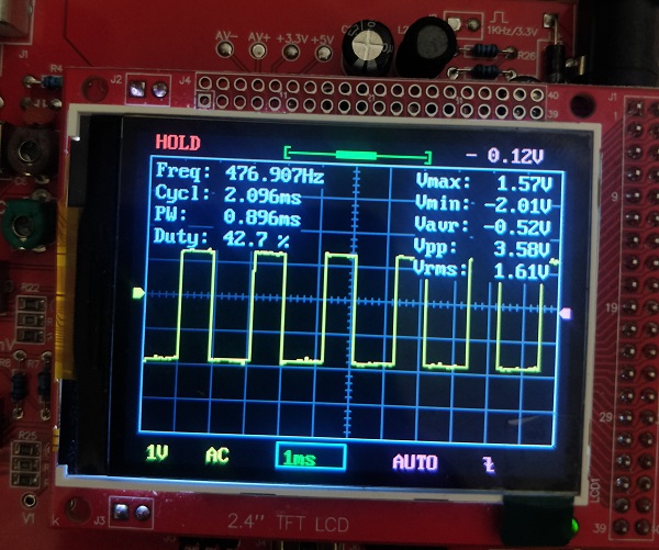
I used the clock divider to be 4. Therefore, the PWM interrupt was being called at $\frac{\text{sys_clk}}{4} = \frac{125}{4}\text{MHz} = 31.25$ MHz. Moreover, 1 PWM cycle consists of 65536 interrupt cycles. Therefore, the PWM frequency that should be generated is $\frac{\text{interrupt frequency}}{65536} = \frac{31.25}{65536}\text{MHz} = 476.83$ Hz.
The scope trace below shows the PWM output from the LED pin. The text in the top left corner of the screen confirms that the frequency of the generated PWM wave is infact 476.9 Hz. We've obtained the expected result.
cmake_minimum_required(VERSION 3.13)

include(pico_sdk_import.cmake)

project(LEDPWM)

pico_sdk_init()

add_executable(LEDPWM LEDPWM.c)

pico_enable_stdio_usb(LEDPWM 1)
pico_enable_stdio_uart(LEDPWM 0)

pico_add_extra_outputs(LEDPWM)

target_link_libraries(LEDPWM pico_stdlib pico_time hardware_irq hardware_pwm)