RP2040 has Dual Cortex M0+ processor cores which can run upto 133MHz independent of each other. However, the second core (core 1) is asleep on boot and needs to be waken up by a function call from the first core (core 0). This program blinks 2 LEDs by controlling them separately from each core. The resources for the project include the C SDK User Guide, the RP2040 Datasheet and Prof. Hunter's website.
/*
 * Parth Sarthi Sharma (pss242@cornell.edu)
 * Code based on examples from Raspberry Pi Foundation.
 * The code wakes up core 1 from its slumber and controles
 * an LED from each core.
 */
#include <stdio.h> //The standard C library
#include "pico/stdlib.h" //Standard library for Pico
#include "pico/time.h" //The pico time library
#include "pico/multicore.h" //The pico multicore library
#include "hardware/gpio.h" //The hardware GPIO library

#define LED1 2 //The LED1 Pin
#define LED2 3 //The LED2 Pin

void core1_entry() { //The program running on core 1
    gpio_init(LED2); //Initialize the LED2 pin
    gpio_set_dir(LED2, GPIO_OUT); //Initialize the LED2 pin to be output
    while(1){ //While eternity
        printf("LED2 On\n"); //Print "LED2 On\n" on the serial monitor
        gpio_put(LED2, 1); //Turn the LED2 on
        sleep_ms(300); //Sleep for 300 milliseconds
        printf("LED2 Off\n"); //Print "LED2 Off\n" on the serial monitor
        gpio_put(LED2, 0); //Turn the LED2 off
        sleep_ms(300); //Sleep for 300 milliseconds
    }
}

int main() { //The program running on core 0
    stdio_init_all(); //Initialize all of the present standard stdio types that are linked into the binary

    gpio_init(LED1); //Initialize the LED1 pin
    gpio_set_dir(LED1, GPIO_OUT); //Initialize the LED1 pin to be output

    multicore_launch_core1(core1_entry); //Reset core1 and enter the core1_entry function on core 1 using the default core 1 stack
    while(1){ //While eternity
        printf("LED1 On\n"); //Print "LED1 On\n" on the serial monitor
        gpio_put(LED1, 1); //Turn the LED1 on
        sleep_ms(500); //Sleep for 500 milliseconds
        printf("LED1 Off\n"); //Print "LED1 Off\n" on the serial monitor
        gpio_put(LED1, 0); //Turn the LED1 off
        sleep_ms(500); //Sleep for 500 milliseconds
    }
}
The first lines of code in the C source file include some header files. One of these is standard C headers (stdio.h) and the others are headers which come from the C SDK for the Raspberry Pi Pico. The first of these, pico/stdlib.h is what the SDK calls a "High-Level API." These high-level API's "provide higher level functionality that isn’t hardware related or provides a richer set of functionality above the basic hardware interfaces." The architecture of this SDK is described at length in the SDK manual. All libraries within the SDK are INTERFACE libraries.
The next includes pull in hardware APIs which are not already brought in by pico/stdlib.h. These include hardware/gpio.h, pico/time.h and pico/multicore.h. As the names suggest, these interface libraries give us access to the API's associated with the hardware GPIO, pico time and pico multicore on the RP2040.
Don't forget to link these in the CMakeLists.txt file!
#include <stdio.h>
#include "pico/stdlib.h"
#include "pico/time.h"
#include "pico/multicore.h"
#include "hardware/gpio.h"
The next section of the code is basically two #define's which define the GPIO pins for the LEDs.
#define LED1 2
#define LED2 3
The core 1 function is the function which runs on the core 1 once it wakes up from its slumber. In other terms, this function is the main() function for core 1 and runs independent of the actual main() function running on core 0 (unless there is an intra-core communication). The core1_entry() function initializes the LED2 pin and configures it to be the output pin. The gpio_init() function is used to initialize the pin and the gpio_set_dir() function us used to set the pin direction which can be GPIO_OUT (output) or GPIO_IN (input). Then, in an infinite while loop, it turns the LED on and off at regular intervals using the gpio_put() function and sleeps for 300 milliseconds using the sleep_ms() function. Note: This will only put core 1 to sleep and not core 0.
void core1_entry() {
    gpio_init(LED2);
    gpio_set_dir(LED2, GPIO_OUT);
    while(1){
        printf("LED2 On\n");
        gpio_put(LED2, 1);
        sleep_ms(300);
        printf("LED2 Off\n");
        gpio_put(LED2, 0);
        sleep_ms(300);
    }
}
stdio_init_all();
In the next 2 lines of the code, I initialized the LED1 pin and configured it to be the output pin. The gpio_init() function is used to initialize the pin and the gpio_set_dir() function us used to set the pin direction which can be GPIO_OUT (output) or GPIO_IN (input).
gpio_init(LED2);
gpio_set_dir(LED2, GPIO_OUT);
In order to wake up the core 1 from sleep, I used the multicore_launch_core1() function. This function resets core 1 and enters the given function on core 1 using the default core 1 stack (below core 0 stack).
multicore_launch_core1(core1_entry);
This is the loop which which runs forever and executes the code sequentially. It basically contains 2 subsections: turning the LED1 on and turning the LED1 off. I also used the printf() statement to print the output to the screen. In order to see the output, I used the serial monitor provided by the Arduino IDE. Then I used gpio_put() to set the pins HIGH or LOW. Lastly, I used the sleep_ms() to put the CPU to sleep for 1 second for both HIGH and LOW. This infinite while loop runs in parallel with the infinite while loop on core 1.
while(1){
    printf("LED1 On\n");
    gpio_put(LED1, 1);
    sleep_ms(500);
    printf("LED1 Off\n");
    gpio_put(LED1, 0);
    sleep_ms(500);
}
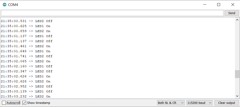
In order to view the output, I used the serial monitor provided by the Arduino IDE. As it shows, the two LEDs are toggling simultaneously.

cmake_minimum_required(VERSION 3.13)

include(pico_sdk_import.cmake)

project(MultiTest)

pico_sdk_init()

add_executable(MultiTest MultiTest.c)

pico_enable_stdio_usb(MultiTest 1)
pico_enable_stdio_uart(MultiTest 1)

pico_add_extra_outputs(MultiTest)

target_link_libraries(MultiTest pico_stdlib pico_time pico_multicore hardware_gpio)