This program was an extension of the introduction to the Programmable Input Output (PIO) on the Raspberry Pi Pico. There are 2 identical PIO blocks in RP2040. Each PIO block has dedicated connections to the bus fabric, GPIO and interrupt controller. These are programmable in the same sense as a processor. There are two PIO blocks with four state machines each, that can independently execute sequential programs to manipulate GPIOs and transfer data. Unlike a general purpose processor, PIO state machines are highly specialised for IO, with a focus on determinism, precise timing, and close integration with fixed-function hardware. The resources for the project include the C SDK User Guide, the RP2040 Datasheet and Prof. Hunter's website.
/*
 * Parth Sarthi Sharma (pss242@cornell.edu)
 * Code based on examples from Raspberry Pi Foundation.
 * The code initializes a PIO state machine on a given
 * GPIO and generates a square wave.
 */

#include "pico/stdlib.h" /Standard library for Pico
#include "hardware/pio.h" //The hardware PIO library
#include "PIOMaxSqaureWave.pio.h" //The pio header created after compilation

#define PIN 6 //Define the GPIO Pin

int main(){ //The main function
    PIO pio = pio0; //Identifier for the first (PIO 0) hardware PIO instance
    uint offset = pio_add_program(pio, &PIOMaxSqaureWave_program); //Attempt to load the program
    uint sm = pio_claim_unused_sm(pio, true); //Claim a free state machine on a PIO instance
    PIOMaxSqaureWave_program_init(pio, sm, offset, PIN, 625.0f); //Initialize the program

    while(1){ //Empty eternity
    }
}
assembly
.program PIOMaxSqaureWave ;Program name

;Generate a square wave on a GPIO pin

    set pindirs, 1 ;Set pin direction to output
.wrap_target ;Free 0 cycle unconditional jump
    set pins, 1 ;Drive pins high
    set pins, 0 ;Drive pins low
.wrap

;Helper function

%c-sdk{
    static inline void PIOMaxSqaureWave_program_init(PIO pio, uint sm, uint offset, uint pin, float clk_div){ //Program to initialize the PIO
        pio_sm_config c = PIOMaxSqaureWave_program_get_default_config(offset); //Get default configurations for the PIO state machine
        sm_config_set_set_pins(&c, pin, 1); //Set the state machine configurations on the given pin
        sm_config_set_clkdiv(&c, clk_div); //Set the state machine clock divider
        pio_gpio_init(pio, pin); //Setup the function select for a GPIO to use output from the given PIO instance
        pio_sm_set_consecutive_pindirs(pio, sm, pin, 1, true); //Use a state machine to set the same pin direction for multiple consecutive pins for the PIO instance
        pio_sm_init(pio, sm, offset, &c); //Resets the state machine to a consistent state, and configures it
        pio_sm_set_enabled(pio, sm, true); //Enable or disable a PIO state machine
    }
%}The first lines of code in the C source file include some header files. The headers which come from the C SDK for the Raspberry Pi Pico include pico/stdlib.h is what the SDK calls a "High-Level API." These high-level API's "provide higher level functionality that isn’t hardware related or provides a richer set of functionality above the basic hardware interfaces." The architecture of this SDK is described at length in the SDK manual. All libraries within the SDK are INTERFACE libraries.
The next includes pull in hardware APIs which are not already brought in by pico/stdlib.h. These include hardware/pio.h and PIOMaxSqaureWave.pio.h. As the names suggest, these interface libraries give us access to the API's associated with the hardware and the custom square wave pio file created in the directory on the RP2040.
Don't forget to link these in the CMakeLists.txt file!
#include "pico/stdlib.h"
#include "hardware/pio.h"
#include "PIOMaxSqaureWave.pio.h"
The next section of the code is basically a single line which #define's the GPIO pin number to read the square wave on.
#define PIN 6
The first line in the main() initializes the PIO instance. The pio_add_program() function loads the program definition and returns the instruction memory offset the program is loaded at. The pio_claim_unused_sm() function is used to claim a free state machine on a PIO instance. Lastly, the PIOMaxSqaureWave_program_init() is called with the given parameters in order to finish configuring the PIO with the given pins and program.
PIO pio = pio0;
uint offset = pio_add_program(pio, &PIOMaxSqaureWave_program);
uint sm = pio_claim_unused_sm(pio, true);
PIOMaxSqaureWave_program_init(pio, sm, offset, PIN, 625.0f);
The infinite while loop for this program is an empty while loop which serves only to keep the core running and not let it exit.
while(1){
}
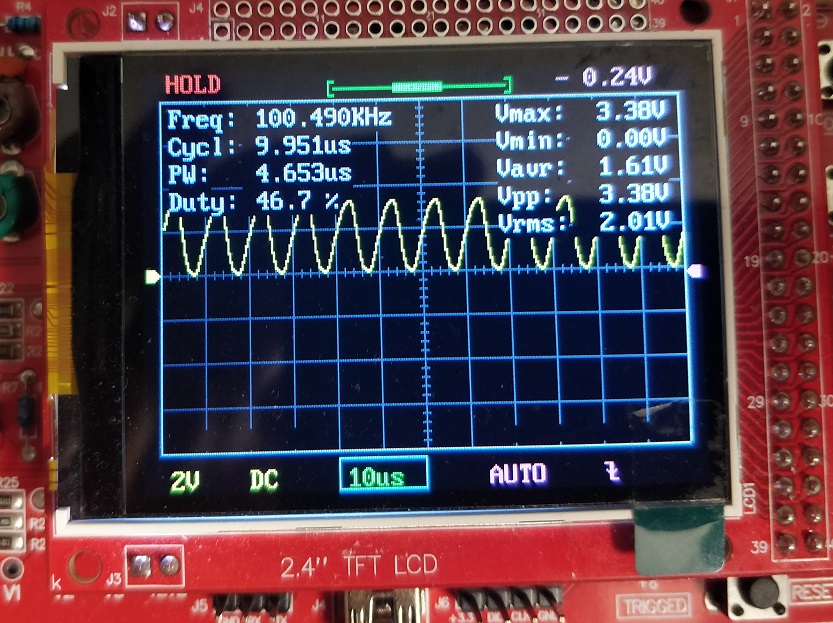
In order to view the output, I used the GPIO pin 6 and attached an oscilloscope to it. Since, the clock divider is 625, the effective clock frequency for the PIO is $clk_{eff} = \frac{\text{clock frequency}}{625} = 200 KHz$. Each instruction takes a clock cycle to execute, therefore, the expected square wave frequency is $sq_{freq} = \frac{\text{200000}}{2} = 100 KHz$.
The scope trace below shows the output from the GPIO pin 6. The text in the top left corner of the screen confirms that the frequency of the generated wave is infact 100.490 KHz. We've obtained a square wave which is quite close to the expected result.
cmake_minimum_required(VERSION 3.13)

include(pico_sdk_import.cmake)

project(PIOMaxSqaureWave)

pico_sdk_init()

add_executable(PIOMaxSqaureWave PIOMaxSqaureWave.c)

pico_generate_pio_header(PIOMaxSqaureWave ${CMAKE_CURRENT_LIST_DIR}/PIOMaxSqaureWave.pio)


pico_enable_stdio_usb(PIOMaxSqaureWave 1)
pico_enable_stdio_uart(PIOMaxSqaureWave 0)

pico_add_extra_outputs(PIOMaxSqaureWave)

target_link_libraries(PIOMaxSqaureWave pico_stdlib hardware_pio)